


Blog
How to Choose Taped Litz Wire for Your Application?
Choosing taped litz wire begins with the operating conditions, not the catalog description. Frequency, current, voltage, and winding geometry all affect the right construction. A coil in a compact power converter may need a different strand size and count than a broad induction winding. Small details matter.
Charles R. Sullivan’s published research on litz-wire winding losses offers a useful design reminder: match the strand construction to the operating frequency and winding geometry. This is a paraphrase of his research, not a direct quotation. From there, compare the tape material, insulation rating, tape overlap, finished diameter, and bend radius. Each choice can affect dielectric protection, heat flow, and how easily the wire fits around a bobbin. Check the termination method, too; a carefully selected cable can still perform poorly if its strands are not joined properly.
A datasheet is a starting point. Ask the supplier for construction details and test data under conditions close to your application. Then confirm temperature rise and winding fit in a prototype. That step can feel slow. It is still cheaper than discovering that the finished coil runs hot or will not sit neatly in its winding window. One caveat: no single taped litz wire construction is best for every design, and supplier claims deserve verification against your actual operating conditions.
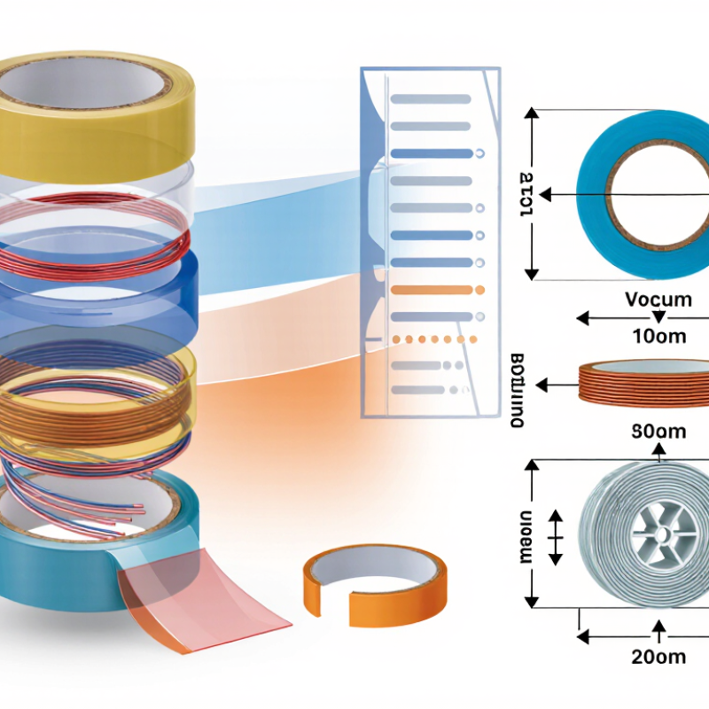
Define Operating Frequency and Strand Size: Copper Skin Depth Is 0.21 mm at 100 kHz
At 100 kHz, copper skin depth is approximately 0.21 mm at room temperature. This is the distance current tends to occupy near a conductor’s surface. Treat it as a useful estimate, not a fixed design limit: temperature, copper properties, and waveform harmonics can change the effective conditions. Very short note: frequency matters.
When selecting taped litz wire, compare skin depth with each strand’s diameter, not the finished bundle’s diameter. A strand comfortably smaller than 0.21 mm is a sensible starting point for reducing skin-effect losses. Then check proximity effects, which can become significant when turns sit tightly together or carry strong magnetic fields. Tape helps hold strands in place and can provide a consistent outer layer, but it does not eliminate copper losses. Its thickness also reduces the copper area available inside a winding window. That detail is easy to overlook.
Tips: Check the actual operating frequency and its harmonics. Confirm strand diameter, tape build, and winding space with the supplier’s data. Test a representative coil for temperature rise and resistance under real operating conditions. A calculation can narrow the choice; it cannot replace validation. There is always some uncertainty.
How to Choose Taped Litz Wire for Your Application?
Define operating frequency and strand size: copper skin depth is approximately 0.21 mm at 100 kHz.
Copper skin depth decreases as frequency increases. At 100 kHz, the approximate skin depth is 0.21 mm. Use this value as a reference when selecting Litz wire strand diameter; actual choices also depend on current, winding geometry, insulation, and thermal limits. Values are calculated for copper at 20°C and are approximate.
Set Strand Count and Copper Area from RMS Current and Allowable Loss
Choose strand count from the required copper area, which starts with the winding’s RMS current. For a rough estimate, divide current by a practical current-density target, then check whether the resulting area fits the bobbin and thermal limits. The target is not universal. Cooling, duty cycle, nearby windings, and insulation all affect allowable loss. Copper loss rises with I²R, so even a small resistance increase can matter at high current. Keep some margin.
Each strand contributes its own copper area; divide the total target area by the area of one strand to estimate strand count. Then consider frequency. Thin strands can reduce skin-effect losses, while tight winding geometry may still create proximity losses. Taped insulation also adds bulk, so compare the finished bundle dimensions with the actual winding window. Small detail, big consequence. A spreadsheet can look precise and still miss hot spots or packing problems. I would question any design that meets its loss target only under ideal cooling. Check winding temperature and resistance in a representative prototype, and revise the strand count if measured results disagree with the estimate.
Select Tape by IEC 60085 Thermal Class: 155°C, 180°C, or 200°C
How to Choose Taped Litz Wire for Your Application?
Select the tape’s IEC 60085 thermal class to match the insulation system’s expected operating conditions. A 155°C class may suit designs with controlled temperatures and adequate cooling. For hotter or more demanding assemblies, 180°C or 200°C materials can provide a higher thermal rating. That number is not a safe operating target for every part. Nearby components, winding density, and poor airflow can create local hot spots. Heat adds up.
Check the complete insulation system, not just the tape label. Wire enamel, tape layers, impregnation varnish, and processing temperatures must be compatible. Ask for test data or supplier documentation confirming the stated thermal class for the finished construction.
In a tightly wound transformer, for example, tape overlap and limited airflow may affect heat removal. Real assemblies are rarely perfect. A higher class can offer margin, but it cannot fix undersized conductors or inadequate cooling. Measure temperatures under representative load, and review the design if results approach its thermal limits.
Specify Tape Thickness, Overlap, and Required Dielectric Withstand
For taped litz wire, specify tape thickness and overlap as separate values. A 25 μm tape with 50% overlap creates roughly 50 μm of tape at the overlapped regions. That changes the finished diameter and can affect slot fill, bend radius, and heat transfer. Small details matter. State whether overlap is measured against tape width or specified as a percentage, and give the allowed tolerance. A drawing that lists thickness alone leaves too much room for interpretation.
Define dielectric withstand on the finished, taped conductor—not just on a tape sample. Specify test voltage, duration, waveform, and conditioning. IEC 60243-1:2013 describes short-time electric-strength testing for solid insulating materials, but it does not set one pass voltage for every winding design. Select the required withstand level from the coil’s operating voltage, switching transients, and insulation system, then confirm it with the supplier. Ask for test records that identify the sample and method. A high test result on a flat coupon may not predict performance at a tight bend or tape edge. That gap is easy to overlook. Check a representative wound sample, especially when overlap, tape thickness, or conductor geometry changes.
Verify Wire Performance with IEC 60851 Tests and Application-Level Loss Measurements
IEC 60851 provides standardized methods for evaluating winding-wire properties, but the relevant tests depend on the taped litz construction. Check dimensions, electrical resistance, insulation performance, and mechanical behavior against the product specification. For taped wire, inspect the wrap for gaps, overlap changes, or damage after bending. Small details matter. Record the sample condition and test setup; otherwise, results can be hard to compare.
A passing test does not guarantee low losses in a finished winding. Measure AC losses at the intended frequency, current, and operating temperature, using a coil geometry close to the real application. Keep winding tension, turn spacing, and lead connections consistent. These details affect results. Compare the taped litz sample with a suitable reference, and measure temperature rise as well as electrical input and output where practical.
Test limits should reflect the application, not just a convenient lab setup. A wire may perform well in a short sample yet behave differently in a compact coil. I would not treat one successful measurement as proof of long-term suitability. Repeat tests across representative samples, and investigate unexpected variation before selecting a construction. A little uncertainty remains, especially when the final winding differs from the test fixture.