What Are the Top Types of Engineering Plastic?
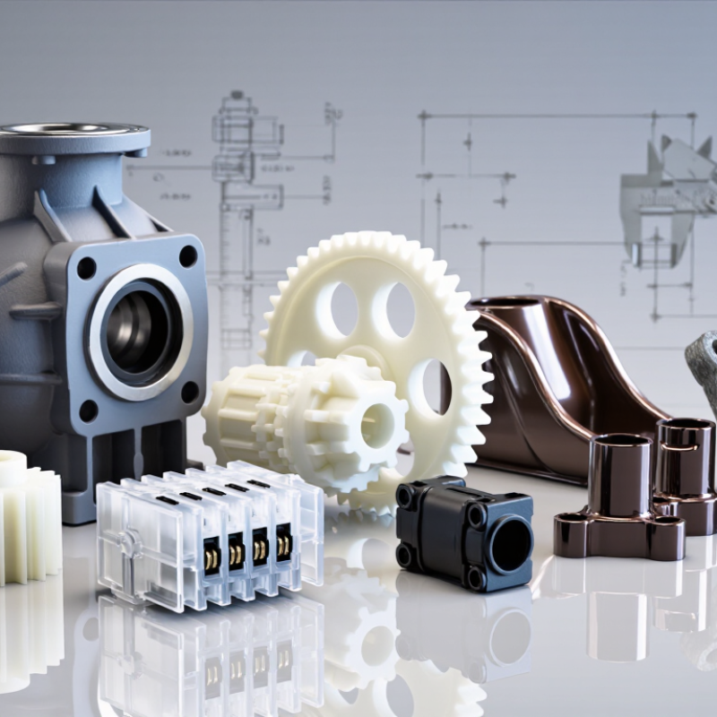
Engineering plastic quietly shapes products that must survive heat, pressure, friction, and repeated impact. It appears in pump housings, electrical connectors, medical components, automotive brackets, and precision gears. Unlike commodity plastics, these materials are selected for demanding performance rather than low cost alone.
Materials scientist Dr. Mark Miodownik once wrote, “Materials are the stuff that makes civilization possible.” His observation explains why engineering plastic deserves careful evaluation. Polyamide, POM, PEEK, polycarbonate, ABS, PPS, and PTFE each solve different problems. A nylon gear may offer strength and practical affordability, while PEEK can retain performance near severe temperatures and chemical exposure. Polycarbonate provides valuable impact resistance, but it may scratch more easily than expected.
There is no universal winner.
This article compares the top types of engineering plastic through measurable properties and real application needs. We will examine temperature resistance, tensile strength, dimensional stability, wear behavior, chemical compatibility, processing requirements, and cost. A material that performs well in a dry laboratory may behave differently beside hot oil, ultraviolet light, or constant vibration. That gap matters.
Some choices remain debatable. Glass-fiber reinforcement can improve stiffness, yet it may increase brittleness or cause wear against mating surfaces. PTFE offers exceptionally low friction, but its load-bearing capability requires careful design. Even experienced engineers can overlook moisture absorption, thermal expansion, or machining tolerances.
The goal is not to promote one resin. It is to clarify trade-offs, expose common assumptions, and support more reliable material decisions. Performance begins with context.
Engineering Plastics: Classifying Materials Above 100°C Service Temperature
Engineering Plastics: Classifying Materials Above 100°C Service Temperature
Engineering plastics are often grouped by their continuous service temperature. This temperature is more useful than a brief peak rating. It shows how a part may perform during long exposure to heat, load, and chemicals. The boundary is not perfectly clean. Moisture, wall thickness, stress, and reinforcement can change results.
Polyamide materials can serve near or above 100°C, especially when reinforced. They offer good wear resistance, but absorbed moisture may reduce stiffness. Polycarbonate provides impact strength and usually handles moderate heat. Polybutylene terephthalate and polyethylene terephthalate offer dimensional stability, electrical insulation, and useful chemical resistance. Their performance depends strongly on processing quality.
Higher-temperature applications often use polyphenylene sulfide, polyetherimide, polyether ether ketone, or selected fluoropolymers. These materials can maintain strength well above 150°C. Some grades tolerate continuous exposure near 200°C or higher. They suit pump components, electrical housings, seals, and precision fixtures. However, a high temperature rating does not guarantee long life. Creep may appear around a bolt hole. A seal may harden after repeated thermal cycling. That detail is easy to miss.
A practical selection review should check temperature, load, friction, chemicals, and moisture together. Test the actual geometry when possible. A material chart is only a starting point. Misjudging one condition can be expensive.
Polyamide PA6/PA66: 50–90 MPa Strength and 120°C Heat Resistance
Polyamide PA6 and PA66 remain practical engineering plastics for gears, housings, brackets, and under-hood components. Published grade data in the CAMPUS polymer database commonly reports tensile strength between 50 and 90 MPa. These values usually describe dry, unreinforced materials tested under ISO 527 conditions. Moisture changes the result.
PA6 generally absorbs more water than PA66. That absorption can improve toughness, but it may reduce stiffness and dimensional accuracy. In real workshops, a freshly molded part can feel rigid, then become slightly softer after humid exposure. This is easy to underestimate. The 120°C heat-resistance figure should also be treated carefully. It usually indicates a practical continuous-service range for selected grades, not a universal limit for every PA6 or PA66 part.
Industry material datasets and supplier-independent technical records often show heat-deflection temperatures above 120°C under specified loads. However, performance declines when heat, stress, moisture, and chemicals act together. The PlasticsEurope Plastics—The Fast Facts 2024 report identifies engineering plastics as a specialized, performance-driven segment, while ISO 527 and ISO 75 testing standards explain why reported values require test conditions. For a compact bearing cage, designers should verify creep, moisture conditioning, wall thickness, and repeated thermal cycling. A 70 MPa datasheet value may not survive the same load after long exposure at 120°C. That gap deserves attention.
Polycarbonate: 600–850 J/m Notched-Izod Impact Strength
Polycarbonate is a leading engineering plastic because it combines low weight with strong impact resistance. Published engineering-material data commonly report notched-Izod impact values of 600–850 J/m. These figures usually follow ASTM D256 procedures, while ISO 180 provides a comparable Charpy-style framework. The values are benchmarks, not guarantees.
That range describes how much energy a notched specimen absorbs before breaking. In practical terms, a 600–850 J/m result suggests useful resistance against sudden knocks from tools, equipment housings, and protective panels. However, test temperature matters greatly. Cold conditions can reduce toughness, while moisture, molding stress, and poor notch quality may change the result. Small details matter.
Material datasheets and industry test reports should state specimen thickness, notch geometry, conditioning time, and test temperature. Without those details, comparisons become unreliable. A 3.2 mm sample should not be compared casually with a thinner one. That is often overlooked. Engineers should also examine tensile strength, heat deflection temperature, and long-term creep before selecting polycarbonate. Impact resistance alone cannot predict field performance. ASTM D256-23 and ISO 180:2023 offer useful reference points, but actual parts still require application-specific validation. Even a strong result may fail after repeated impacts or exposure to chemicals.
What Are the Top Types of Engineering Plastic? — Polycarbonate: 600–850 J/m Notched-Izod Impact Strength
| Engineering Plastic |
Typical Density
(g/cm³) |
Tensile Strength
(MPa) |
Tensile Modulus
(GPa) |
Notched-Izod Impact Strength
(J/m, ASTM D256) |
Heat-Deflection Temperature
(°C at 1.8 MPa) |
Common Engineering Uses |
| Polycarbonate (PC) |
1.20–1.22 |
55–75 |
2.1–2.5 |
600–850 |
125–140 |
Safety glazing, machine guards, electrical housings, transparent components, impact-resistant parts |
| Acrylonitrile Butadiene Styrene (ABS) |
1.03–1.07 |
35–55 |
1.7–2.6 |
150–350 |
75–100 |
Equipment housings, automotive interior parts, appliance components, consumer products |
| Polyamide 6 (PA6) |
1.12–1.15 |
55–85 |
2.0–3.2 |
80–180 |
55–95 |
Gears, bearings, cable ties, structural brackets, wear-resistant components |
| Polyoxymethylene (POM) |
1.40–1.43 |
60–75 |
2.5–3.5 |
50–110 |
95–115 |
Precision gears, rollers, bushings, pump components, low-friction mechanisms |
| Polybutylene Terephthalate (PBT) |
1.30–1.33 |
50–70 |
2.2–3.0 |
50–150 |
120–165 |
Electrical connectors, sensor housings, automotive components, appliance parts |
| Polyphenylene Sulfide (PPS) |
1.34–1.36 |
65–90 |
3.0–4.0 |
25–80 |
190–260 |
High-temperature electrical parts, chemical-processing components, automotive under-hood parts |
| Polyetherimide (PEI) |
1.27–1.30 |
85–115 |
3.0–3.5 |
50–110 |
170–210 |
High-temperature housings, medical components, electrical insulation, aerospace interiors |
| Polyether Ether Ketone (PEEK) |
1.30–1.32 |
90–105 |
3.5–4.2 |
50–100 |
140–160 |
High-performance seals, bearings, chemical-processing parts, aerospace and medical components |
|
Data note: Values are representative ranges for unfilled injection-molding grades tested near room temperature. Actual results depend on grade formulation, specimen geometry, moisture conditioning, molding direction, temperature, and test method. Notched-Izod results are shown in J/m; many laboratories report the same impact measurement in kJ/m², so the units and specimen standard should be checked when comparing materials.
|
POM and PTFE: Low Friction, from 0.1 Coefficient to 260°C Service
What Are the Top Types of Engineering Plastic?
POM and PTFE remain practical choices when sliding resistance matters. ASTM D3702-based tribology data commonly reports POM friction coefficients near 0.1–0.3 under dry, moderate-load conditions. PTFE often measures around 0.04–0.1.
These values change with pressure, speed, surface finish, temperature, and material grade. A polished steel shaft can behave very differently from a rough one.
It stays slippery. PTFE also tolerates continuous service near 260°C, according to widely published engineering-plastic thermal data and ISO 11357 testing references. However, high temperature can increase deformation and wear. POM normally suits continuous operation near 100°C, with short-term exposure sometimes reaching approximately 120°C. It offers better stiffness and dimensional stability than PTFE in many room-temperature assemblies. ASTM D3702 and ISO 7148-2 provide useful frameworks for comparing friction and wear in sliding components.
A neat comparison can mislead. I would not treat 0.1 as a promise. Actual bearing performance depends on load cycles, lubrication, mating surfaces, and moisture.
PTFE may reduce startup friction, but its softness can cause creep under constant pressure. POM can provide a firmer running surface, yet it is less suitable near 260°C.
Engineers should request test data using the intended load, velocity, temperature, and counterface. Small changes matter.