





Blog

What Is a Concentric Reducer Fitting?
A Concentric Reducer Fitting is a pipe component that connects two pipes with different diameters. Its centerlines remain aligned along one common axis. This symmetrical design creates a gradual transition between the larger and smaller pipe. It is widely used in process piping, water systems, chemical plants, and industrial equipment.
The shape is simple.
In practical installation, the larger opening receives the incoming pipe, while the smaller opening continues toward downstream equipment. This arrangement can support balanced flow and clean routing. However, it may also create a vertical or horizontal change in pipe elevation. That effect deserves attention during layout planning. A careless installation can increase air accumulation, drainage problems, or unwanted pressure behavior.
Selecting the correct fitting requires more than matching outside diameters. Engineers and fabricators should verify material grade, wall thickness, pressure rating, temperature range, and connection method. Common options include carbon steel, stainless steel, alloy steel, and specialized corrosion-resistant materials. Butt-weld dimensions may follow recognized standards, such as ASME B16.9, but project specifications still control final acceptance.
Real-world experience shows that drawings can hide important details. Welding access, insulation thickness, support spacing, and corrosion allowance may change the best choice. That explanation is incomplete without considering the entire piping system. A trustworthy guide should connect the fitting’s geometry with installation practice, inspection requirements, and long-term service conditions. This article examines those factors clearly, while recognizing that application-specific engineering review remains essential.
Definition and Basic Function of a Concentric Reducer Fitting
What Is a Concentric Reducer Fitting?
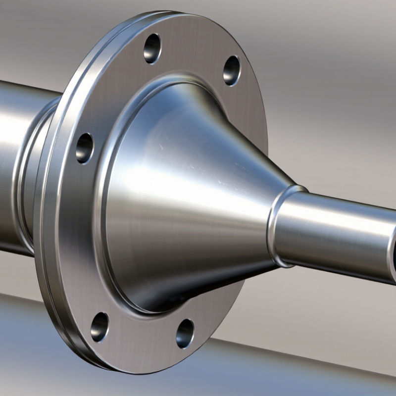
A concentric reducer fitting joins pipes with different diameters on one shared centerline. Its tapered body changes the flow area gradually. The larger opening accepts the incoming pipe, while the smaller opening connects to the downstream line. This basic geometry keeps the pipe axis straight and supports balanced installation around the centerline.
In practical piping work, engineers use concentric reducers in vertical lines, pump discharge systems, and process networks. The fitting can reduce space requirements and simplify alignment. However, it does not automatically eliminate turbulence or pressure loss. Flow rate, reducer angle, surface roughness, and fluid viscosity still matter. That detail is often overlooked.
ASME B16.9 provides dimensional requirements for many factory-made butt-welding fittings. Material specifications and inspection records add reliability during procurement. Grand View Research’s 2024 pipe fittings market analysis estimated the global market at about 13 billion U.S. dollars in 2023, with continued growth expected through 2030. This wider market trend reflects sustained demand for dependable flow-control components, not proof that every reducer performs equally.
A field check should confirm diameter, wall thickness, material grade, connection type, and installation direction. Small errors matter. A reducer installed backward can create avoidable flow problems. In some horizontal liquid lines, an eccentric reducer may manage air pockets better, so a concentric design should not be selected by habit alone. That decision deserves review.
What Is a Concentric Reducer Fitting? - Definition and Basic Function of a Concentric Reducer Fitting
| Data Dimension | Factual Information | Basic Function or Practical Significance |
|---|---|---|
| Definition | A concentric reducer is a pipe fitting that connects two pipes with different nominal diameters while keeping both pipe centerlines on the same axis. | It provides a controlled transition from a larger pipe size to a smaller pipe size or from a smaller size to a larger size. |
| Geometric Shape | The fitting has a symmetrical, cone-shaped body with a large end and a small end sharing the same central axis. | The centered geometry creates an even transition around the flow path and maintains a straight axial layout. |
| Size Description | Size is normally stated as the larger nominal pipe size followed by the smaller nominal pipe size, such as 6 in × 4 in or DN150 × DN100. | The size description helps match the fitting to the connected pipes and the required change in flow area. |
| Primary Flow Effect | In a reducing-flow direction, the fluid velocity generally increases as the available internal flow area decreases, subject to the flow rate and actual internal diameters. | It allows a piping system to adapt the flow passage to downstream equipment or a smaller branch connection. |
| Flow Transition | The tapered wall creates a gradual diameter change instead of an abrupt step between pipe sizes. | A gradual transition can help reduce severe local turbulence and sudden flow separation compared with an abrupt diameter change. |
| Centerline Arrangement | The large and small ends are aligned concentrically, so the pipe centerline remains continuous through the fitting. | This arrangement is useful where axial alignment, balanced geometry, or a symmetrical flow path is important. |
| Typical Connection Ends | Common end configurations include butt-weld ends, socket-weld ends, threaded ends, and flanged ends, depending on the piping design. | The end type determines the joining method, installation procedure, inspection requirements, and compatibility with adjacent components. |
| Common Materials | Concentric reducers may be manufactured from carbon steel, stainless steel, alloy steel, ductile iron, copper alloys, or engineering plastics. | Material selection depends on pressure, temperature, corrosion exposure, fluid compatibility, mechanical loading, and applicable piping requirements. |
| Typical Applications | They are used in process piping, water systems, fire protection systems, HVAC piping, power facilities, chemical services, and general industrial pipelines. | The fitting connects different pipe sizes while preserving a compact, in-line piping arrangement. |
| Vertical Installation | A concentric reducer is often suitable for vertical piping because its centerline remains aligned through the size transition. | It can simplify vertical routing and is commonly considered where eccentric offset is unnecessary. |
| Horizontal Installation Consideration | In horizontal lines, the symmetrical shape may allow liquid to collect at the lower transition or gas to remain at the upper transition, depending on orientation and service conditions. | Engineers should evaluate drainage, venting, phase behavior, pump suction conditions, and the possibility of vapor pockets before selecting the fitting. |
| Pressure and Temperature Rating | The allowable pressure and temperature are determined by the material, wall thickness, connection type, design standard, and service conditions. | The fitting must be selected using the applicable rating requirements rather than by nominal size alone. |
| Standards and Dimensions | Outside diameters, wall thicknesses, face-to-face dimensions, and tolerances vary according to the governing dimensional and manufacturing standard. | The project specification and applicable standard should be checked to ensure dimensional interchangeability and proper fit-up. |
| Main Advantages | Compact in-line design, continuous centerline alignment, simple size transition, and broad availability in multiple materials and connection types. | These characteristics make concentric reducers practical for many general-purpose piping layouts. |
| Selection Checklist | Verify nominal sizes, actual outside diameters, wall thickness, material, connection ends, pressure-temperature rating, fluid compatibility, installation orientation, and governing standard. | A complete review helps prevent leakage, misalignment, excessive pressure loss, corrosion, vibration, and unsuitable drainage or venting conditions. |
